Citroen Relay ECU repair – story
- November 5, 2025
- 0 Comment(s)
Once upon a time, a company van broke down.
Citroen Relay 2.2 HDi PUMA 96
I was driving along when the EML popped up and limp mode activated – max 2000 RPM. I pulled into a lay-by, plugged in the diagnostic interface, and checked the stored DTC:
P0480 13 – Fan assembly 1 control circuit.
I didn’t have time to deal with it, so I cleared the fault and carried on driving. The lack of one fan wasn’t an issue that day, I just needed to monitor the engine temperature. No issues for the next half hour, but then it came back.
Some time later it became too frequent – every 10 seconds I had to turn the engine off and start again while driving. So I pulled into a safe parking lot, turned the engine off, and began troubleshooting. I pulled the wiring diagrams and checked the continuity of the wire from the ECU to the fan 1 fuse – OK. Fuse to relay – OK. Even though the DTC said “control circuit,” I had no other ideas, so I carried on checking continuity between the relay and the fan – that was also OK. Checked the fan on direct feed – it worked.
All these measurements took some time as I had to pull many things off for access, but having checked the entire fan 1 circuit and confirmed it working, I put everything back together and tried to start the engine. That’s when the real circus began.
On ignition I was greeted with a message on the screen saying “Excess radiator fluid temperature.” The temperature gauge went immediately to max, then returned to minimum, but the actual temperature reading was correct (ambient). Both fans started running at full speed. I also got the warning light indicating water in fuel, and the starter motor wouldn’t crank at all.
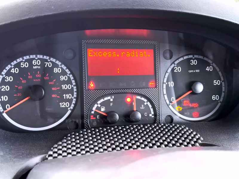
Excess radiator fluid temperature message on the screen
So the most obvious logic was – I’d messed something up. The initial problem was one fan, and now I had four different problems that seemed unrelated to the original one. It couldn’t be a coincidence, it had to be my fault. Most likely I hadn’t pushed one of the ECU plugs fully back in – that would explain a few seemingly unrelated faults. But no, I checked the plugs several times – no problem there.
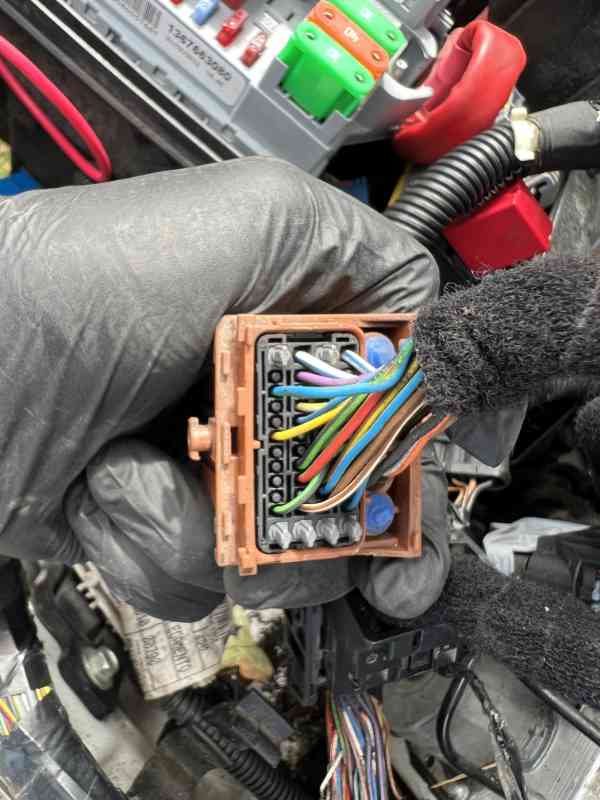
One of ECU connectors
After some time, once I convinced myself that it wasn’t my fault but something else, I checked for DTCs:
P0606 47 – Engine management ECU
P0383 72 – Pre-post heat unit control module
P0615 13 – Starter motor relay circuit
P2264 01 – Water in diesel sensor
P0480 13 – Fan assembly 1 control circuit
P0481 13 – Fan assembly 2 control circuit
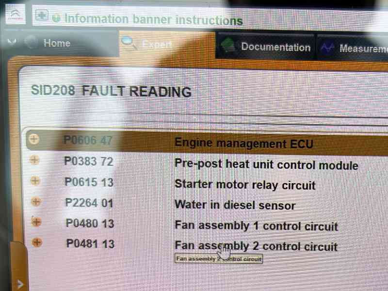
Stored DTCs
The last two were irrelevant, I pulled both fuses to disable the fans as they were running constantly for no reason.
I started looking at wiring diagrams for the water-in-diesel sensor, starter motor relay circuit, and glow plug control module. What those three had in common was that they were connected to the same plug at the ECU – but that didn’t tell me much at that moment. The coolant temperature sensor was also connected to the same plug. The water sensor and glow plug unit shared one ground point, so I thought that was very likely the problem. Ground chassis connections can get rusty, that’s not uncommon.
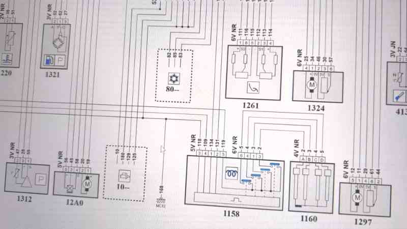
Part of wiring diagrams showing common ground point
The starter motor relay wasn’t connected to the same ground point, but I was hoping that was either a discrepancy in the wiring diagrams (as they’re not always 100% accurate) or something I simply didn’t understand at the moment. Checking the ground point doesn’t take much time, so I did. This one was underneath the N/S lamp, and I was almost sure that’d be it.
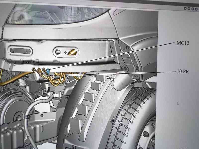
Ground connections locations
It was not.
I checked the starter motor relay and discovered that the wiring diagram was correct – the relay’s ground is connected directly to the ECU, same plug. However, the resistance relative to chassis ground was around 30 Ω, which would become important later.
After checking the wiring continuity between the ECU and the water-in-diesel sensor, starter motor relay, and glow plug module (it was obvious the wiring wasn’t the problem, but I had no other ideas and needed to check everything 100%), I pulled the ECU out – a SID208 – and disassembled it. At that point I knew that whatever had failed, I wouldn’t be able to fix it in the field, so I had to call a tow truck back to the workshop.
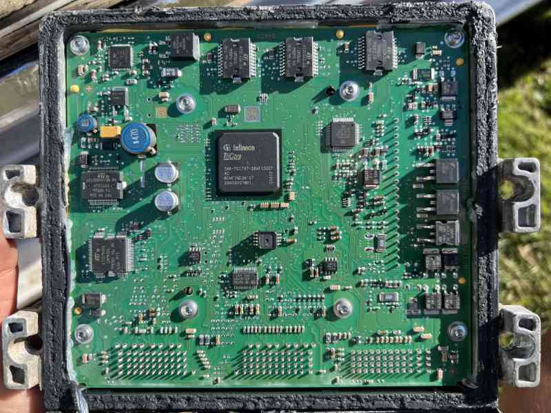
ECU SID208 PCB view
Repairing an ECU is much more difficult than repairing an instrument cluster. It contains many proprietary ICs. There’s no documentation publicly available, so full reverse engineering isn’t possible. But let’s see if it’s even necessary.
Checked the starter relay connection – it goes directly to one of these ICs, so that’s where our troubleshooting of that circuit ends. We can’t go any further without knowing what that IC is or how it’s arranged. Next connection: water-in-diesel sensor – same IC. OK, I’m starting to get excited. Glow plug module – same IC. Temperature sensor – same IC. So we found a common denominator.
That still doesn’t mean the IC has failed – it might not have power to a particular bank of I/Os, or might not communicate with another IC, or any number of other external reasons. But again, we’ll never know without a datasheet, which we’ll never have access to.
Measuring one of the outputs, which should be the emitter of an internal transistor, its resistance relative to ground should be 0 Ω – but it read 30 Ω. The same resistance was measured at the starter relay ground. If the reading had been 1 kΩ or 10 kΩ I could assume an internal pull-down, but 30 Ω made no sense. So I was now sure that this IC had failed.
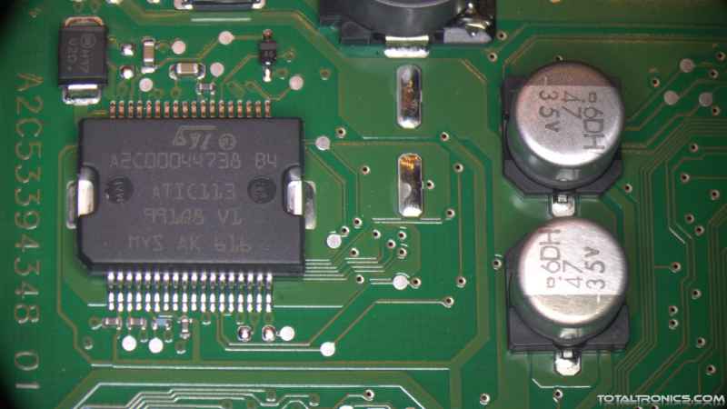
Finally, a diagnosis! But what do we do with it? Where do we get that IC? You can’t just buy it from an electronics wholesaler – only directly from the manufacturer, and only if you’re calling from Continental AG to place an order for a million units.
Another way is to salvage it from a second-hand unit, but the cheapest one on eBay that might be the same (you won’t know until you open it, and then you can’t return it if it’s different) was about £600. The 99% matching unit was over £1000. We didn’t want to spend that much, especially with the risk the unit could still be slightly different – you can’t tell just by comparing labels.
In such a case you could still replace the whole unit and code it to the vehicle, but you’d need to find someone capable of coding it. Not only is that difficult, but it adds another few hundred pounds. Fortunately, we have a large chain of suppliers, and one of them was able to supply the IC. We replaced it and got the van back on the road.
