A professional repair service for your Land Rover Range Rover Sport instrument cluster.
Supported cars:
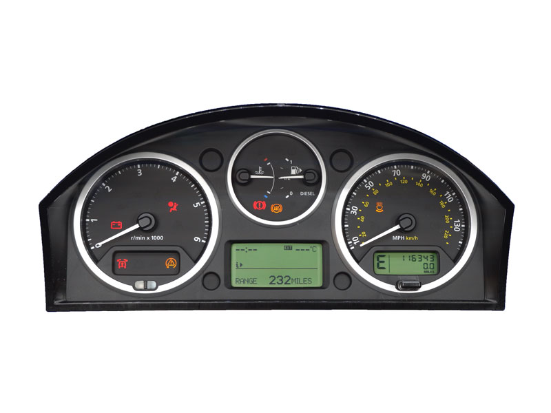
- Range Rover Sport (L320) (2004-2009)
Common faults:
- intermittent power loss
- total power loss – dead instrument cluster
- non starting issue
- partial or total loss of background illumination
- blank LCD display
- flashing hazard lights while driving
- doors locking/unlocking themselves
- oil warning light ON, passengers seat belt warning on, “Low screen wash fluid” message shows on display and no warning indicators for front and rear fog lights
- CAN bus communication issues
We fix all of above faults.
We use only brand new high quality parts to fix your cluster, which we fully test before it’s shipped back to you.
Your mileage reading stays the same so there’s no need for extra coding.
We provide a lifetime warranty.
Turnaround is 2 days if we receive it by 1 pm, which is possible if you send it by Royal Mail Special Delivery for £11. So if you send it on Monday, you’ll receive it on Thurdsay by 1 pm. In some circumstances we may be able to repair it within the same day. Please let us know if it’s urgent.
We also offer a While You Wait repair, which takes about an hour. This is arranged by appointment only.
What do you need to do then? Just send your dash pod to us or bring the car and leave it with us. We will take the cluster out and fit it back in after repair, all in less than an hour.
Brand new Range Rover Sport clusters are not available anymore nowhere in the world, even though your dealer may tell you they are on back order.
Do not buy second hand instrument cluster, it won’t work in your car. You will spend a lot more money for the cluster, coding and repair as the other one will fail in the same or other way. We fix many clusters from customers who already bought another one and tried to code it with no success.
Please feel free to call us on 01305 534 080 or email at support@totaltronics.com if you have any questions regarding this repair service.
Price includes UK shipping.
Technical information about Anti-Theft – Passive system:
The engine immobilization system uses the instrument cluster, as a gateway for communications with the ECM.
Operation of the engine immobilization system is automatic and requires no input from the driver. The engine
management system will only crank and run the engine when a valid key is in the ignition switch.
When it senses a key in the ignition switch the CJB energizes the transponder coil, which activates the transponder. The
transponder transmits identification and rolling code data to the CJB. The CJB checks the data from the transponder
against stored data to validate the key. When the ignition switch is turned to position II (ignition), the ECM sends a start
authorization request to the CJB. If the key is valid the CJB grants the request and the ECM will subsequently crank and
run the engine. If the key is invalid, the CJB refuses the request and the ECM will not crank the engine.
TRANSPONDER
The transponder is an integral part of the Printed Circuit Board (PCB) located within the head of the ignition key. For
additional information, refer to Handles, Locks, Latches and Entry Systems (501-14 Handles, Locks, Latches and Entry Systems)
The transponder is powered by a rechargeable battery and is contained within the processor on the PCB, which also
controls the remote operation of the Central Locking System (CLS). A separate coil on the PCB is used by the
transponder to receive the signals from the transponder coil on the ignition switch. The coil is also used to generate the
current required to recharge the battery.
The transponder has a 256 byte Electronic Erasable Programmable Read Only Memory (EEPROM), which is
programmed with vehicle identification data and a unique identification code. This information is stored in one of 30 key
‘slots’ within the CJB. When energized, the transponder emits the coded information which is received by the CJB. The
CJB checks that the key is valid by confirming the received data before granting permission to start the engine.
TRANSPONDER COIL
The transponder coil is located in a plastic housing which surrounds the ignition switch barrel. The transponder coil is
connected via two wires to the CJB. The CJB emits electrical energy to the transponder coil which transmits data at a
frequency of 125 kHz. This electrical energy excites the transponder in the ignition key when it is within 20 mm (0.78 in) of
the transponder coil.
CJB
The CJB is the main component in the immobilization system. The CJB contains a processor and software which controls
the immobilization system. The CJB is connected to the medium speed Controller Area Network (CAN) bus, which it uses
to communicate with the ECM via the instrument cluster and the high speed CAN bus.
When the ignition key is placed in the ignition switch key barrel, the immobilization system wakes up. The transponder coil
is activated causing the transponder to transmit its coded data. The CJB validates the data and transmits another request
for the data. When this is received for a second time, the CJB confirms the key as valid.
When the instrument cluster fails, CJB is not able to communicate with the ECM and it is impossible to start the engine.